
In the previous part of the crank rebuild, I removed the motor from the frame and split the cases, at this particular time I will concentrate on removing the main bearings as well as replacement of seals and gaskets. At this stage of disassembly it is wise to check over your transmission for wear, particularly the shifting dog's if they are bent or rounded at the ends. In my particular engine the shifting dogs looked good so I opted to leave them alone.
Since the cases are now split and the crank is out, the majority of the transmission can stay intact if your not going to do any work there. When the motor is in first gear the transmission can stay in the right case, but two gears on the primary shaft and one gear on the secondary shaft must come out as well as a couple of washers.

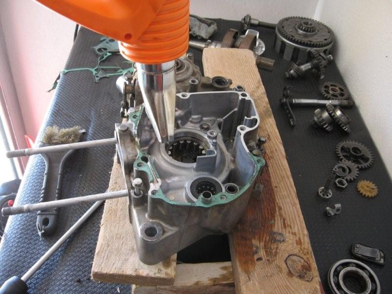
Take note on how they came out, if you mix them up, then you can always refer to the Honda microfiches on www.yeltirk.com as to the order that they should be assembled. Remove the bearing stay (ears that hold the bearings in place) WITH AN APPROPRIATE PHILPS TIP!!! The last thing you want to do now is strip these bolts! If you have a bearing press you're too cool for school, but for us NON millionaires we have to do it the caveman way. Once the ears are out, turn the right side case over and place it on the 2X4 engine box that we built earlier. Heat the case AROUND the bearing for about eight to ten minutes, then using an appropriate sized socket on an extension I drive out the bearing from the clutch side of the case (refer to Pic)

if you notice in the picture, I also left the old main seal in place to help "keep" the socket or "bearing driver" centered.
The ball bearing in the right side case using the above method should come out without any problems after heating, and in my case, the bearing dropped out on its own after about 8 minutes of heating the case with a heat pistol set at 600 Celsius. (if your using a heat pistol do not allow the tip to go any closer than 7cm from the material.
as you can see above the same process is applied to the lefthand crank case, where I heat the area around the bearing to expand the hub holding the bearing for about eight to ten minutes only on this side I have to take out the seal as its ID is too small to accommodate a large enough driver to act on the cylindrical roller bearings.

At this stage I put a beer, and the new crank and main bearings in the freezer, meanwhile I concentrated on cleaning up all gasket, sealing surfaces, and threads of the bolts which hold the cases together, taking my time since the crank and bearing have to cool down anyway. Once everything's all cleaned up I take the beer out of the freezer and drink it "enjoyingly" (I know that's not a word) and whip out the heat pistol once again, using it to heat up the bearing hub on the right side (clutch side) case for eight to ten minutes

after im done heating it up, I run to the freezer and pull out the right side BALL bearing (be careful! My ball bearing came with the outer race recessed (cut away) on one side to accommodate the bearing stays (ears which hold the bearing in place) this has to be facing up when you install it in the case so that the stays can be properly installed (in the pic the bearing was installed BACKWARDS! so be careful!!!). Make sure the case is well supported and use the old bearing as a driver to install the new bearing into the case.

You will know when the bearing bottoms in its recess by a denser sound when hammering on the driver. I went around the circumference with a socket extension and hammer to make sure its bottomed uniformly. Once the bearings in place I apply a drop of thread locker on the threads of the bearing stay bolts and torque them down to their respective values (refer to above pic). The next step is to heat up the right side case AND newly installed bearing (make sure you don't install the new main seal yet since the heat from the heat pistol will damage the new seal).

AGAIN heat up the bearing now for eight to ten minutes, then run to the freezer and get your crank out, it should just drop in, if it doesn't put the crank back into the freezer, reheat the bearing and repeat! Do not hammer on the opposite end of the crank (you will damage the oil jet) . the crank should noticeably bottom when slid into the right side bearing. the installed crank will look as follows:

You can see how cold the crank is in the pic by the frost forming over it. NOW we can install the right side main seal, greasing it a bit around the circumference to help it slip in. At this point place the right case assembly (right side case with crank and tranny) aside and concentrate on getting the new cylindrical roller bearing into the left side case. Again heat the hub in the left side case which holds the bearing for a good eight to ten minutes (you can see this in a pic posted above) support the case with the motor bench constructed earlier, I used some extra planks to increase contact surface area while I drive in the new bearing. Immediately after heating I pull out the new bearing from the freezer and place it into position it should slid in a bit if not completely, check around the circumference of the bearing to see where you may have a "high spot" and hammer via the old bearing in this area, recheck for high spots and adjust you hammering position, repeat this process until the bearing bottoms, identified by a denser sound when driving in the bearing.install the main seals. If you are changing the secondary transmission shaft seal ( the seal on your drive sprocket shaft), balancer shaft seal, and shifter shaft seal, do it now as no further heating is required. The beauty of the four stroke design is that you don't have to do any further heating, and you don't have to worry about "pinching" the crank on assembly. The crank should just slip into the left main bearing when it comes time to close the cases.
Remembering that we removed three gears and some washers, Again refer to the Honda microfiches on the internet if you forgot the assembly order of these parts. Reassemble them into the right side case assembly.
I find it wise to install the new piston at this time before the cases are together just incase a pesky piston clip decides to find its way into your cases when assembled.

With the piston in, its time to install the center case gasket , making sure that all dowels are in place. set it over the right side case and install the left side case from above. Make sure all shafts are lined up and get the cases as close as possible being very careful to have an even gap between both cases. Once it wont go any further by hand, I begin to install the center case bolts and tighten them in a crisscross pattern making sure that the case gap is always as even as possible, moveing to and from each bolt until I slowly get the cases together as evenly as possible. Once both cases are in contact I hand tighten with a screw driver type "driver" (sorry I cant explain it any beter) again tightening in a crisscross pattern. now HOLD ON! before torquing to spec! now is a good time to install the shifter shaft WITH shifter and shift through all gears. If you cant! then theres something wrong (some effort may be required to shift as well as turning one of the transmission shafts while shifting to get the tranny to shift into gear, remember theres no oil yet) during this process, if the gears are not shifting correctly i havent "squished" the center case gasket yet and i can reuse it if i have to take the cases apart again. if alls good, then finally I tighten them down to spec with a torque wrench. And voila my cases are together.

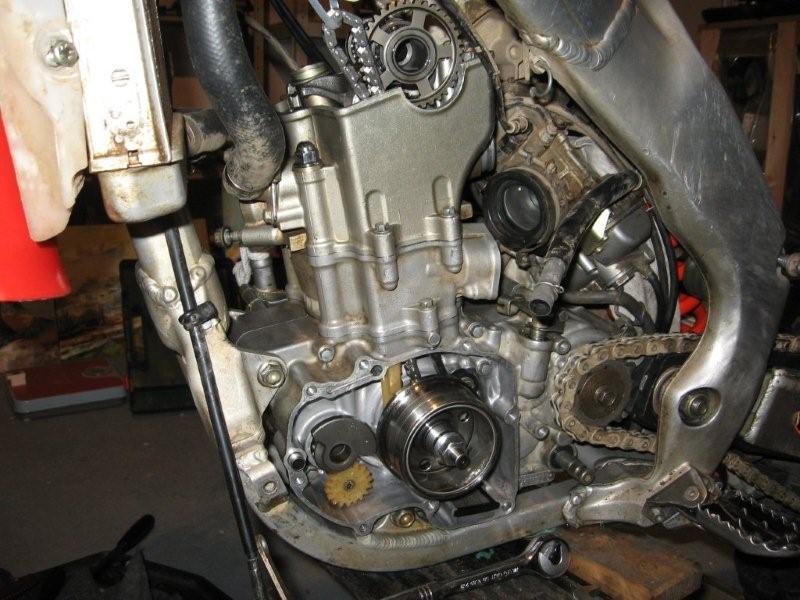
right now its the reverse process of taking it all apart! i will give just some basics of the reassembly. if you notice in the pic above i have the flywheel puller protective cap skrewed on over the oil jet on the end of the crank. this will prevent me from accidentaly damaging it. put on all the guts of the clutch side of the engine, main gear, counterbalancer gear and make sure they line up.
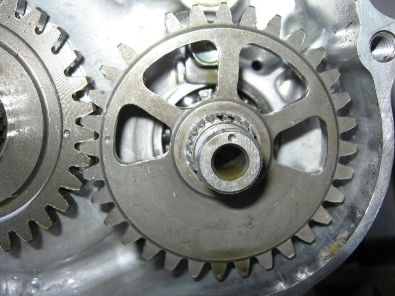

before installing the balancer shaft, assemble the oil pump idler gear and pin (plastic gear) on right side case, the gear is held on the pin when the balancer shaft is installed, instal it now. Now go to the other side and be CAREFULE! take notice that the main gear has a "missing" or "filled down" tooth as well as a missing spline on the end of the crank shaft. these should meet up in order for the gear to properly indicate TDC! install the retainer skrew and hand tighten. The balancer shaft spline and gear "teeth" have this same indication for the proper position, but also make sure that the gear dimples on the main gear and balaner gear line up as in the pic above! instal the retaining nut, and hand tighten. instal the kick start idler gear if it was removed, then the clutch basket and inner hub in the order that you dissassembled: collar, bearing, hub, spacer, then inner hub (remember! if you forgot or messed up the order of assembly then refer to static images, microfiches, of the clutch assembly on the internet) install retaining washer and nut, hand tighten.


prep the left crank case cover and replace all seals etc, and take special care not to loose the coper washers located on the water pump shaft, there are two!
at this stage i put the motor (whats assembled of it at least) into the frame, this will allow me to tighten the retaining bolts and washers. i tighten the clutch basket and drive sprocket the same way i took them off, by blocking the rear sprocket (refer to crank rebuild part 1). after the clutch is torqued down (remember to bend down the tab to "lock" the nut in place) its would be good to install the push rod and push rod "end cap". however, now the main gear counter balancer and flywheel are tightened a bit differently. first off remember to take off the woodruf key (for your flywheel) from your old crank (they dont supply a new one with your new crank) its time to put in our NEW cam chain and derailer, followed by the cylinder gasket then cylinder, and THEN the cam chain tensioner guide! (installing the guide before the cylinder can risk damage to the guide as i found out the hard way!):


install the head and pull the cam chain through the cavity and keep it there with a skrew driver or zip tie it to the frame. and install the cam chain derailer as well as the flywheel (you have to take off the protective puller cap to do this now.) install washer and hand tighten the retaining nut.

NOW we can start torqueing things down. the highest torque value is on the main gear retaining bolt on the right side of the engine. get someone to hold that bolt with a socket. torque down the balancer retaining nut right next to the main gear, then go on and torque down the flywheel retaining nut on the other side and torque that down. finally in order to torque the main gear to proper specs, you need a "jammer" which wedges between the main gear and the counterbalancer gear. i improvised by using a piece of HARD WOOD! cut into a wedge. refer to pick:

i know i was also surprised it worked too. after this is done, put in the kick starter spindle! (there is a certain position which should be retained if you want the appropriate spring return force, i just refered to pics that i made before dissassembly. heres mine:

note the position of the C-shaped retaining spacer on the iner part of the spring, and remember that there is another copper washer on this spindle, refer to any microfiches online and make sure that its INSIDE when you put on your left engine cover.
instal the right side engine cover and instal your clutch friction disks and plates. install the kick starter and check if it has the proper return rate. reassemble the right side cover with stator, and hook up your electrics. line up your motor to TDC and install your cam, make sure its timed correctly and take your time here! (there is a great proceadure here on CRF's only to do this in the HOW-TO section) check your valve clearances. once alls good install you tensioner


Hook up the cooling hoses and reassemble the rest of the bike (i feel its not necessary to go any furthur). add liquides, and a clean air filter. if you where patient, and double, sometimes tripple checked everything, your bike should fire up in a couple of kicks as mine did. break the sucker in and ride like youve never rode before, im so tired right now, i need a beer and a good nights sleep.

ALSO! i just want everyone to know that this is an engine rebuild done MY WAY! if there are any errors in the proceadures or methodology of this post please let me know, and i will make the necessary changes. I would hate to pass on bad practice principles to fellow CRF's Only members. also id like to improve Crank rebuild part 1, when i have some time. finally thanks to posts by LITHIUM and others, i will list some of the torque specs for some of the more crucial bottom end fasteners:
1. RHS Crank bearing bolts 12Nm/9ft-lb (20Nm/14ft-lb after 2006)
2. Main shaft bearing bolts 9.8Nm/7ft-lb
3. Gear drum bearing bolts 9.8Nm/7ft-lb
4. Bolt for plate for Kick starter assembly
5. Pin for the gearshift spindle (crankcase stopper pin)8.8Nm/6.5ft-lb
6. Balancer shaft bearing bolts 9.8Nm/7ft-lb
7. Flywheel= 64Nm (47 lb ft)
8. Main Gear= 108Nm (80 lb ft)
9. Counter balancer= 44Nm (33 lb ft)
10. Clutch Basket Center Nut= 69Nm (5l lb ft)
11. Output Sprocket= 31Nm (23 lb ft)